
ARP to Musitronics Mu-Tron III Modification
by: Whirl-A Sound
The Mu-Tron III changed my life. I'd just started college and was living in a small apartment in town when I began seriously getting into the Grateful Dead. I embraced all the things Deadheads do, and before long, I had embarked on the envelope filter tone quest. My ex-girlfriend patiently endured my using the stove as a soldering surface while I was learning electronics—I’ll always appreciate her for that.
Long story short, it took many years of experimenting with envelope filters, mods, comparisons, and more before I finally acquired a genuine vintage Mu-Tron III. By that time, my circumstances had changed; I was pursuing a full-time education in electronics and could finally conduct some meaningful analysis.
The ARP Mu-Tron III is very similar to the Musitronics model, with the most noticeable difference being its internal power supply. However, as Mike Beigel noted in a statement released about the ARP Mu-Tron III in 2011, the power supply itself is significantly different. You can find that statement at the bottom of this blog post.
When I received my ARP Mu-Tron III, it honestly sounded terrible. I had purchased it from a well-known pedal seller on Reverb, and unfortunately, the power supply was in very poor condition. It had undergone substandard repairs, which explained the poor sound quality (an excessively fast sweep due to incorrect calibration and power supply modifications producing voltages of +14V and -8V—unusable for the Garcia tone). Initially, I planned to rebuild it according to ARP specifications, as a somewhat blurry schematic does exist. Eventually, though, I had a simpler idea: convert the ARP Mu-Tron III into a Musitronics Mu-Tron III with a built-in PS-1. The ultimate Mu-Tron!
The Power Supply

The original Musitronics Mu-Tron III operated on a bipolar 9V supply powered by a half-wave rectifier from a 24VAC transformer. The ARP version, however, employs an 18VAC transformer with a bridge rectifier to deliver a 12V bipolar supply. Being a purist, I opted to stay true to the original PS-1 design.
The primary challenge I faced was sourcing a suitable 24VAC, 85mA transformer compact enough to fit inside the Mu-Tron III casing. Here's what I found:
Hammond 166C24 (24VAC CT @ 85mA): Discovered on 12/12/23, this appears to be the closest match, although the other transformers mentioned also work fine.
Stancor P-8394 (24VAC CT @ 85mA): This transformer provided the best sonic results in my tests (yes, power transformers do affect tone). However, it must be a vintage production unit. The newer "Made in Thailand" version has a casing and laminations that contact the chassis bottom, bending the circuit board due to size. The older models labeled "STANCOR" in block letters fit exactly like the original transformer and are highly desirable, though harder to find. Ultimately, this is the transformer I used in my ARP Mu-Tron III.
Hammond 187A24 (24VAC CT @ 100mA): This transformer fits well within the casing, but careful insulation of the leads is necessary because it uses solder lugs instead of standard lead wires. This was the transformer I used in the initial clone build of my modded vintage Mu-Tron III—had I known earlier, I might have started with this option from the beginning.

The bad fitting P-8394 on the left, good fitting version on the right.
The rest of the modification is straightforward. You need to convert the bridge rectifier to a half-wave rectifier by removing the two unnecessary diodes. Next, update the Zener diodes to 9.1V, 1W types (I used 1N4739A). The last components for the power supply are four .01µF shunt capacitors—two for each rail. These are already part of the original design, so no additional action is needed.
An important note: You do not need to upgrade the 220Ω resistors to 2W if you are modifying an ARP unit. Initially, I was puzzled by the presence of these resistors in the PS-1 design. However, I eventually understood that they serve a dual purpose: setting the Zener diode current and providing protection for the power supply. If the power supply outputs were shorted, these resistors would dissipate just over one watt, protecting the power supply from damage—an ingenious design that effectively uses what would otherwise be undesirable source resistance.
This protective scenario exists in the original PS-1 because it is separate from the Mu-Tron unit. In the ARP modification, however, the condition does not occur due to the integrated design, and the fuse provides sufficient protection. While you may choose to upgrade the resistors as I initially did, it's not strictly necessary.
Envelope Generator Response
You'll need to change resistor R19 from 240k to 180k, as it forms part of the voltage divider responsible for allowing the filter to sweep downward at the correct depth and sensitivity. This resistor is located beneath one of the switches and can be identified by its color code. Near the original 240k resistor, there are also two 1.5k resistors—one in series with the optocoupler's cathode variable resistor (likely there to prevent damage) and another for the effect LED. These resistors represent upgrades to the original circuit, and I chose to keep them.
Additionally, if you decide to adjust the decay to the stock value, you'll need to replace the 68k decay resistor with a 47k resistor.
To better understand the impact of these modifications, let's briefly review how the Mu-Tron's optocoupler affects the audio signal. Consider an upward sweep effect: each optoresistive element is parallel with a 220k resistor, establishing the filter's "heel down" baseline. When you pick the strings, the envelope generator circuit activates an LED inside the optocoupler, illuminating brighter with stronger picking. This light reduces the resistance of the two photoresistors inside the optocoupler significantly below the 220k baseline (potentially down to about 1k, depending on the specific optocoupler). This reduction creates the characteristic "upward" sweeping sound of the filter.

Keeping this concept in mind, here is an oscilloscope capture demonstrating the envelope generator circuit in action. The image shows three notes played on my guitar, illustrating how the circuit transforms the wavy AC sine wave into a DC signal that modulates the LED.

Both channel 1 and 2 are hooked to the same signal. I have channel 1 inverted to show the representation of the incoming signal as more of an “AC waveform.”
Understanding this concept is crucial for calibrating the optocoupler current. The pedal's 25k trimmer controls the current supplied to the optocoupler, and while the envelope generator triggers the LED, improper current levels—either too high or too low—can result in limited dynamic range. The objective is to identify the optimal setting or "sweet spot."
It's important to remember that a faster sweep results in more high-end frequencies, as the photoresistor becomes saturated with light. Conversely, a slower sweep produces fewer high-end frequencies due to lower illumination and consequently higher resistance from the photoresistor. Grasping this principle is essential to effectively dialing in an optical-based envelope filter.
Visualizing this effect can aid understanding. Below is a frequency response chart of my Mu-Tron clone set to bandpass mode. Each line represents a frequency response measurement, with the effect's input level stepped in 2 dB increments:
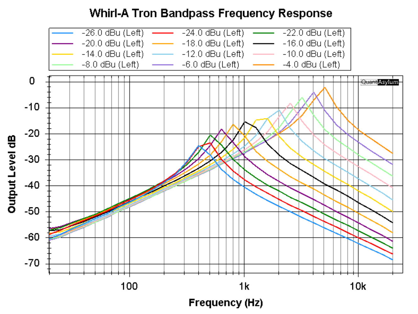
You can see that a higher input level changes the pedal's frequency response by shifting the Q to a higher or lower frequency.
Calibration
Here is a procedure to calibrate the Mu-Tron III based on the Big Box Q-Tron Calibration procedure. I feel this gets you back to a calibration that feels “stock.”

Envelope Generator Speed and Response Mods
The classic modification for slowing down the optocoupler response in Q-Trons involves adjusting the R18 decay resistor from its original 47k value to 68k. The ARP Mu-Tron III originally used a 68k resistor, likely because the later Hamamatsu optocouplers were faster than the original 805A models used by Musitronics in the mid-1970s. However, your preference might differ—try using 47k first and see which suits your style better.
Mike Beigel's Q-Tron+ from the 1990s replaced the standard 330-ohm attack resistor with a 2k resistor in its "slow" setting.
At this stage, it's crucial to spend ample time playing and experimenting with the pedal. Because this pedal responds directly to picking dynamics and touch sensitivity, you'll need to get a feel for its response. Personally, I prefer using the combination of a 330-ohm attack resistor with a 68k decay resistor alongside the P873-14 optocoupler, although optocouplers themselves present an additional layer of complexity which I'll explore further another time.

My Mu-Tron has also been updated for true bypass, but i’d like to revert it soon as i’ve been told the preamp in bypass is a “thing.”
Here's that blip from Mike Beigel:
"By the time ARP was making Mu-Tron IIIs, I was already out in my own (Beigel Sound Lab) consulting and product design business again, and i never paid much attention to the ARP Mu-Tron products. (They are the Mu-Tron III products WITH the AC line cords, and labeled as produced by Mu-Tron INC. (not Musitronics Corp. which made them from 1972 to 1978."
Last night (January 17) while working with my colleague Richard Lingenberg on some new product design work, we got to talking about the ARP (Mu-Tron INC) units, and I got a BIG and DISAPPOINTING surprise. I had always figured that they were competent enough to make the product the way I had originally designed it, but that was WRONG."
To make this brief, Richard (who gets all my Mu-Tron Vintage repair work and his own repair work from other sources) has fixed up and calibrated a lot of these ARP units.
Apparently, they changed the inside POWER SUPPLY VOLTAGE but in doing so, they apparently DID NOT UNDERSTAND to change some component values that were designed for the ORIGINAL power supply voltage.
What Richard noticed about (ALL?) the ARP units coming in for repair, was that the FREQUENCY SWEEP was WAY TOO HIGH.
And also that the DOWN DRIVE never really worked to drive the filter down "all the way" as it was supposed to.
Both of these symptoms had to do with changing the power supply voltage but not compensating for the change by changing ALSO some very critical component values.
So Richard (who knows what a Musitronics Mu-Tron III unit SHOULD sound like), changed the offending parts values and recalibrated the SWEEP range and DOWN DRIVE to what they were designed to be.
I never knew about this before, and am sharing it now. If you have an ARP Mu-Tron III and don't like the way it sounds or works, now you know why.
If you want it to be fixed (even though it's not officially "broken" and recalibrated, please send me a note at <info at mu-tron dot ORG (NOT .com), and I will forward the information to Richard, who will contact you and give you a quotation on fixing the parts values and re-calibrating it to the frequency sweep range of the original factory Musitronics Mu-Tron Calibration.
(But if you are perfectly happy with your ARP-Mu-Tron unit, then by all means USE IT AS IS. Richard also noticed enough variation in the calibration of the ARP units that it's just possible that YOUR vintage ARP-MuTron III unit is accidentally calibrated "just fine".
There weren't all that many ARP units made, but I thought it appropriate to inform the owners of these vintage (and AUTHORIZED by Musitronics Corp) i.e. LEGITIMATE reissues, that there might be issues with the units that (I) didn't know till last night.
Thanks,
Mike Beigel"
Last updated: 12/23/24